IVH PCB
Features
- IVH realizes small/high density design.
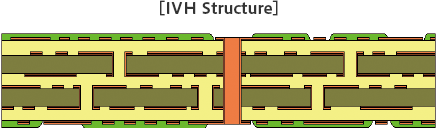
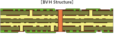
- Customer can pick from three types (IVH, BVH, IVH-BVH hybrid) to suit their needs.
- Continuous support from development/design stage to suggest the best production design.
Structure
Standard Specification
| Item | Type | |||
|---|---|---|---|---|
| IVH | BVH | IVH-BVH Hybrid | ||
| Thickness [mm] | 4 layer | 0.4–1.6 | 0.5–1.2 | - |
| 6 layer | 0.8–1.6 | 0.8–1.2 | 0.8–1.2 | |
| 8 layer | 1.6 | 0.8 | 0.8 | |
| Min. L/S [μm] |
Outer layer: 100/100 Inner layer: 100/100 |
Outer layer: 125/125 Inner layer: 100/100 |
Outer layer: 125/125 Inner layer: 100/100 |
|
| Hole (Drill) Diameter [mm] |
IVH | 0.30–0.35 | 0.30–0.35 | 0.30–0.35 |
| Through Holes | More thann 0.30 | More thann 0.30 | More thann 0.30 | |
| No. of Connectable Layers | 4 layer | 1-4/2-3 | 1-4/1-2/3-4 | 1-4/1-2/3-4 |
| 6 layer | 1-6/2-3/4-5 | 1-6/1-2/5-6 | 1-6/1-2/3-4/5-6 | |
| 8 layer | 1-8/2-3/4-5/6-7 | 1-8/1-2/7-8 | 1-8/1-2/3-4/5-6/7-8 | |
| Thickness of Copper[μm] Cu Foil + Cu Plating Thickness |
Outer layer: 32–49 Inner layer: 35/32–49 |
Outer layer: 39–56 Inner layer: 35/24–34 |
Outer layer: 39–56 Inner layer: 24–34/32–49 |
|
Contact us for other specifications.
Properties
| Item | Test Conditions | Results |
|---|---|---|
| 1. Solder Heat Resistance | Solder Floating (260[°C]/120[sec]) | No Problem |
| 2. Withstand Voltage | 1. Between Circuits: D.C100[V]/1[min] 2. Between Layers : 0.80[mm] Less Than D.C500[V]/1[min]: 0.80[mm] More Than D.C1000[V]/1[min] |
No Dielectric Breakdown |
| 3. Insulation Test | 1. Between Circuits: D.C100[V]/1[min] 2. Between Layers : 0.80[mm] Less Than D.C100[V]/1[min] : 0.80[mm] More Than D.C500[V]/1[min] |
1. Between Circuits 1.0×10⁹[Ω] More Than 2. Between Layers 1.0×10⁹[Ω] More Than |
| 4. Moisture Resistance Test | 1. Between Circuits : 40[°C]/90[%RH]/D.C100[V] Continuous Application/1000[hr] 2. Between Layers : 40[°C]/90[%RH]/D.C100[V] Continuous Application/1000[hr] | 1. Between Circuits
1.0×10⁹[Ω] More Than
2. Between Layers 1.0×10⁹[Ω] More Than |
| 5. Migration Resistance Test | 1. Between Circuits : 85[°C]/85[%RH]/D.C50[V] Continuous Application/240[hr] 2. Between Layers : 85[°C]/85[%RH]/D.C50[V] Continuous Application/240[hr] | 1. Between Circuits 1.0×10⁹[Ω] More Than 2. Between Layers 1.0×10⁹[Ω] More Than |
| 6. Thermal Shock Test | 1. Gas Phase Test -65±3[°C]/30[min] : 125±3[°C]/30[min] 100[Cycles] 2. Liquid Phase Test 260+5-0[°C]/10[sec] : 20±5[°C]/20[sec] 50[Cycles] | 1. Gas Phase Test Change rate of conductor resistivity Less Than 4.5% 2. Liquid Phase Test Change rate of conductor resistivity Less Than 8.0% |
| 7. BVH Pad Adhesion | Share Test Pad Diameter: φ0.45mm(BVH Diameterφ0.25mm) |
Breaking During Soldering More than 800 [g] |
Above numbers are actual measurements as a reference, not assurance of quality.